ARTEX is security research software where a large language model (LLM) determines the next action, and execution tools and repositories carry out that decision. Rather than executing a predefined list of commands once after inputting a goal, it is closer to a repetitive structure of plan → execute → observe → replan.
To understand this structure, it’s faster to look at the journey of a single request rather than folder names. We will examine where the goal entered on the screen is stored, who creates the tasks to be executed, and how the tool’s results return to the next model call.
The analysis is based on the fixed commit 9e1b227d73a6881c1455b0e5ee0595e669474ed2 of the Korean fork jiwoochris/artex-ko. This explanation is confirmed by reading the source and dependency code, and it is not the execution result of LLM automated security testing or a post-mortem of vulnerability discovery. Analyzed Source

Conceptual image generated by AI. Not an actual ARTEX screen or execution result.
1. Screen, Execution Engine, and Model Perform Different Tasks
The main flow of ARTEX is as follows: observation results return to the worker’s model conversation, and stored results are also used for the planner’s next plan.
목표 입력 → 작업 생성 API → 저장·목표 분해 → 계획자
                                           ↓ 실행할 일
                                         작업자
                                           ↓
                                  LLM 호출 ↔ 도구 실행·결과
                                           ↓
                                  사실·발견 저장 → 다음 계획
                                           ↓
                                      화면·보고서
WRIMO-MD-TABLE-0]The server program configures the Manager and HTTP server in cmd/artex/main.go. The API called by the browser and the backend that calls the model are separated. Core task data is stored in PostgreSQL, and separate file storage paths are also used for conversation history and command artifacts. Interpreting this flow as SQLite being the main operational DB just because go.mod has a SQLite dependency would be a misreading. [Program Entry Point · DB Connection Code
2. Goal Input Does Not Immediately Become a Shell Command
Let’s assume a goal was entered for a hypothetical isolated practice service: “Check the security headers of the specified HTTP response and mark any unconfirmed items separately.” This example is for explaining the flow and is not an actual test performed.
The frontend’s api.createTask sends input to POST /api/tasks. The server’s createTask verifies request items such as JSON and model settings, then calls Manager.CreateTaskWithOptions. Here, the task and its exploration history are linked. The API returning a task ID is a separate event from goal achievement. Frontend Request · Task Creation Processing
Subsequently, launchTask inserts initial information and passes it to the path that determines the task’s executability. startTaskEngine, which initiates execution, decomposes the goal, and after its results are ready, calls Engine.Run. This sequence is a structure designed to reduce situations where the planner reads a goal that doesn’t yet exist. If goal decomposition using the model fails to produce results, there is an alternative path that uses the original goal as is. Start/Goal Decomposition Path
Engine.Run starts one planner loop and a configured number of worker loops per task. The default flow is planning first. However, if initial tasks were pre-inserted with the seed_first_intent option, workers might take them on first, and subsequent results could wake up the planner. Therefore, it cannot be assumed that all tasks necessarily start with the first planner call. Execution Engine Start
3. The Planner Creates Tasks, and the Worker Records Results
The intent created by the planner here is “a specific task to be performed next.” If the goal is security header inspection, it could be “read the headers of the specified response and record the confirmed items.” Separating the goal from the tasks to be executed allows the overall goal to be maintained while changing subsequent tasks based on observations.
Planner.Plan constructs the model input with changes that have occurred, the current state of the exploration graph, and the remaining goals and task list. The model can add tasks to be executed or mark goal achievement through exposed tools. The MainAgent, which interacts with humans, is responsible for conveying observations, hints, and instructions, while this autonomous planning loop is the planner’s responsibility. Planning Input and Tool Configuration · MainAgent Role
Workers pick up pending tasks. ClaimIntent in the DB changes only nodes with an ‘open’ status to ‘running’ and verifies if a row was actually modified. This ensures that even if multiple workers see the same candidate, only the worker successful in this status change takes on the task. Task Assignment · DB Status Change
There are two types of relationships in the repository: The exploration graph records how goals, tasks to be executed, observed facts, and discoveries are connected. The asset graph records what was handled, such as services and endpoints. Exploration nodes and assets are linked to track “through which task and on which target this observation was made.” This represents data relationships as a graph and does not imply the use of a separate graph DB. Node, Link, Asset Link Schema
When a worker’s execution finishes, the results are saved, and NotifyDone wakes up the planner. There is also a separate notification path for registering findings. The planner collects multiple change notifications and processes them in a single planning cycle, and if there are no changes, it wakes up again through periodic checks. Re-planning uses both reactions to results and periodic checks. Planner/Worker Loop
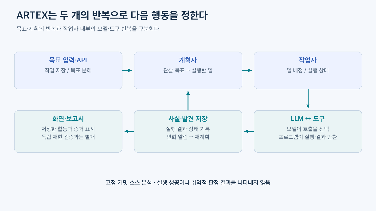
Figure 1. Reconstructed based on the execution engine and worker code of the Korean fork. Simplifies the relationship between planning, execution, and observation, and is not an execution demonstration result.
4. The Model Selects Tools, and the Program Executes Them
Worker.execute creates model input from the assigned task, related assets, constraints, and current situation. Specifically, the assigned task is placed in the system prompt to maintain the execution purpose even if long conversations are compressed. The tool list includes graph recording tools, file/shell tools, and additional tools are assembled according to settings. Worker Execution Configuration
ARTEX delegates agent execution to the norma v0.4.3 SDK. captureRunSession drives the session’s Prompt and receives model responses and tool execution events. The model connection configures calls with the selected model, API address, and communication format. Therefore, ARTEX itself is not an LLM; the configured model service generates judgments. Dependency Version · Model Connection · Session Driving
The basic loop observed in the SDK is as follows:
- Pass the current conversation and the names/input formats of available tools to the model.
- If the model returns a tool name and arguments, the program finds the registered tool.
- Verify input format, permissions, and pre-execution hooks, then call the actual tool.
- Add output or errors as tool_result to the conversation.
- The model reads the results and chooses the next call or termination.
In the hypothetical example, the result of reading the HTTP response returns to the model. If headers were checked, that observation can be recorded as a fact. If the connection failed, the next decision must be made with the result “check impossible.” An observation of HTTP 200 alone does not lead to the conclusion that the entire service is safe or vulnerable.
Tool calls returned by the model are execution requests. Actual shell commands are performed by the SDK’s process execution code in the execution environment. Specifying a directory per task is also a setting related to file organization and execution location, not a feature that creates OS-level isolation itself.
5. Approval Rules and Execution Environment Boundaries Must Be Considered Together
The worker session sets the SDK permission mode to ModeBypass. This is a setting where basic SDK approval questions cannot be assumed to be bypassed. Meanwhile, the engine connects ARTEX’s Guard hook to the worker, so separate interception rules can handle execution requests. Permission Mode Setting · Worker Hook Connection
Guard.applyIntercept evaluates rules for target tools to handle allow, deny, and ask. ‘ask’ waits for human approval. However, if there is no interception object or the tool is not subject to interception, this path does not block it. There is a path that allows if the rules do not match and LLM-assisted review is off or disconnected. Blocking rules are meaningful only when settings and connection status are also checked. Actual Branch
Notably, the Planner.Plan in the source code read does not show code connecting a Guard hook to options like the worker, yet the default tool list includes shell tools. The existence of a worker approval path should not be extended to guarantee that the same controls apply to all tool calls of all agents. This is why role-specific tools and hook connections need to be reviewed separately. Planner Tools/Execution Options
A safe first practice can be designed in a dedicated environment with only synthetic data, targeting a single owned and authorized HTTP service. Model communication and practice service communication should be separated, and other access restricted in the execution environment. Do not connect business files, browser profiles, or host control interfaces, and first define short time limits, call budgets, and interruption methods. This is a practice design to be verified in the future, and this code analysis does not claim that such controls are actually working.
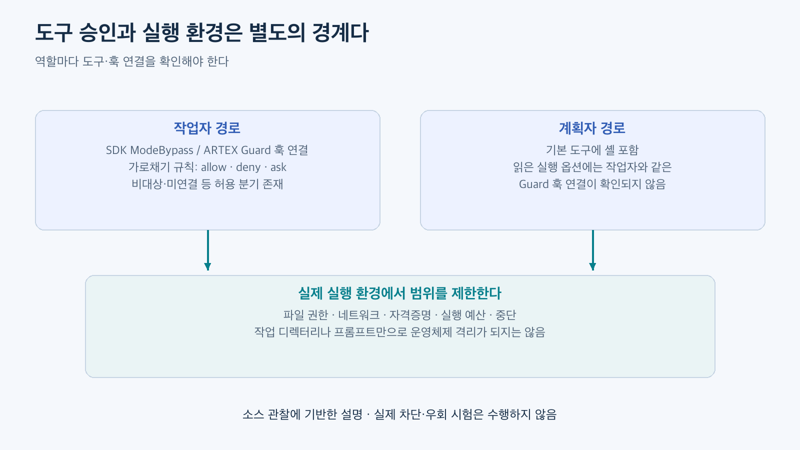
Figure 2. Reconstructed based on the Guard branch and planner options of the Korean fork. This is an observation of the source at a fixed commit and no actual blocking/bypass tests were performed.
6. Reasons for Stopping Are Also Recorded as Status
Pausing cancels the execution context and prevents worker loops from taking on new tasks. The planner can also use steer_work to adjust ongoing tasks and kill_work to stop them. The termination of the overall task and the termination of individual tasks to be executed are managed separately. Interruption/Intervention Code
Normal worker termination is generally recorded as ‘done’, errors as ‘blocked’, and reaching turn count or execution time budget as ‘exhausted’. At budget exhaustion, the system is configured to record already confirmed information in a final stage where shell tools are hidden. This distinguishes the state of running out of time from goal achievement. Termination Status Branch · Worker Finalization Settings
This status management does not mean that all external side effects are rolled back. Already completed HTTP requests or file changes are separate from cancellation signals. This is also why execution targets, file permissions, and network scope are kept small when using the interruption feature.
7. From Which Code Does “Confirmation” in the Report Originate?
During execution, captureRunSession converts tool calls, tool results, text, termination, and usage events into activity records. The server stores these and delivers them to the screen via SSE, i.e., by sending server events while maintaining the connection. Optionally saved model conversation logs and HTTP logs passed through a proxy are different types of evidence. Proxy settings alone cannot guarantee that all network communications of all tools are recorded. Activity Capture · Screen Event Transmission
When interpreting results, the most important distinctions are completion of tasks to be executed, goal achievement, and verified reproduction of vulnerabilities. prove_goal checks if the specified goal is a goal node of this task and if the evidence is a readable fact/finding node. It then links the evidence and goal and changes the goal status to ‘met’. If all goals reach this state, task completion is determined. Independent re-execution verification of the evidence content within this function is not confirmed. Goal Judgment Code
report_finding also requires the same caution. The description states to submit confirmed vulnerabilities with evidence. However, the RecordFindingTx function verifies the affiliation of the task, exploration, and task to be executed, and stores the submitted content in the exploration node with a ‘confirmed’ status. A separate ‘findings’ record uses the default ‘pending’ status. The name ‘confirmed’ for an exploration node does not mean that this storage path has reproduced and validated a vulnerability as true. Submission Tool · Storage Transaction · Findings Table
Automatic linking of HTTP evidence is also configuration-dependent. If it’s off, findings can be saved without evidence reference arguments, and if there’s no actual link, there’s a path that returns evidence_status: not_bound. Evidence Linking Branch
The source also contains a path to initially configure a reporter agent that reads execution records and evidence to write detailed reports upon finding registration. This path is affected by agent, tool, and trigger settings. Meanwhile, the Markdown renderer formats stored findings and evidence into a report. Writing a report and independently reproducing and verifying evidence should be distinguished. Reporter Configuration · Report Rendering
Therefore, when reviewing results, the model’s conclusions, actual requests/responses, normal comparisons, and reproduction conditions must be read together. Even simple observations like missing headers only lead to security conclusions if the necessary context and impact of that item are confirmed. ARTEX’s iterative structure automates the process of generating next investigation directions and collecting evidence, but automated execution and verified vulnerabilities must be evaluated based on their respective merits.
The standard for this article is the fixed Korean fork mentioned above, not the original last confirmed public version v0.3.15 or the preserved fork gasbugs/ARTEX. Due to differences in core agent/engine files even in minimal comparisons, this explanation cannot be directly applied to all versions of the original. The root LICENSE of this commit is the full AGPL v3, which is the same as the original version compared. The quality of Korean output in the Korean version is guided by language instructions, so it is not guaranteed by the structure alone. LICENSE · Korean Version Description
Leave a Reply