When studying Kubernetes, you’re bound to wonder, “I just typed the kubectl create deployment command, but how exactly does my container appear on a specific node?”
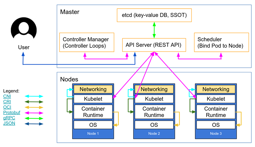
Today, through a Kubernetes architecture diagram, we will thoroughly explore the entire journey from a user’s request, through the Master (Control Plane), to the actual creation of a container on a Node (Worker Node). 🕵️♂️✨
https://kubernetes.io/blog/2018/07/18/11-ways-not-to-get-hacked/
1. Master Area: Receiving Commands and Drawing Blueprints 🧠
Every journey begins at the user’s keyboard and heads towards the API Server on the Master node.
1️⃣ User Request (User → API Server)
- Action: The user requests the creation of a Deployment via a kubectl command or UI.
- Protocol: The request is transmitted to the API Server via HTTP communication in JSON format. (Blue arrow in the diagram 🟦)
- Role: The API Server is the ‘gateway’ of the Kubernetes cluster and the central hub for all components.
2️⃣ Information Storage (API Server ↔ etcd)
- Action: The API Server validates the request and then stores this information in etcd.
- Role: etcd is a Key-Value store that holds all cluster data and is the SSOT (Single Source of Truth). Now, the Deployment is recorded in the cluster’s ‘Desired State’.
3️⃣ Controller Design (Controller Manager)
Now it’s the Controller Manager‘s turn to get busy. (Purple arrow in the diagram 🟪)
- Deployment Controller: Detects new Deployment information and requests the creation of a corresponding ReplicaSet (RS) from the API Server.
- ReplicaSet Controller: Detects the created RS and requests the creation of Pod objects equal to the configured number of replicas.
- Point: ⚠️ Important! The Pod information created at this stage is merely a data chunk in a Pending state, with “which node it will go to (nodeName)” still empty.
4️⃣ Scheduling (Scheduler)
- Action: The Scheduler finds lonely Pods without a nodeName. (Purple arrow in the diagram 🟪)
- Logic: It checks the resource status of the nodes (Filtering) and selects the most suitable node (Scoring). For example, let’s say ‘Node 2’ is chosen.
- Binding: The Scheduler updates the API Server with binding information: “This Pod goes to Node 2!”
2. Node Area: Bringing Blueprints to Reality 🏗️
Now the stage shifts to the Node (Worker Node) where actual workloads will run.
5️⃣ Kubelet Receives Mission (API Server → Kubelet)
- Action: Kubelet, acting as the captain of each node, periodically communicates with the API Server to check (Watch) if there are any Pods assigned to its charge (Node 2).
- Protocol: This communication primarily uses Protobuf (gRPC) for efficiency. (Purple arrow in the diagram 🟪)
- Upon confirming new Pod assignment information, Kubelet begins the actual creation process.
6️⃣ Laying Network Roads (Kubelet ↔ CNI)
Even if a container is created, it’s useless without communication, right? Let’s set up the network first.
- Interface: Kubelet calls the network plugin via the CNI (Container Network Interface). (Sky blue arrow in the diagram 🟦)
- Result: The Pod is assigned an IP and a communicable network environment is configured.
7️⃣ Container Execution Request (Kubelet ↔ CRI)
Network preparation is complete, so it’s time to create the actual container.
- Interface: Kubelet issues commands to the container runtime (Containerd, CRI-O, etc.) via the CRI (Container Runtime Interface).
- Protocol: This process is carried out via gRPC communication. (Green arrow in the diagram 🟩)
8️⃣ Process Execution on OS (Runtime ↔ OCI ↔ OS)
- Action: The Container Runtime, upon receiving the request, pulls the image and communicates with the Linux kernel (OS) according to the OCI (Open Container Initiative) standard. (Yellow arrow in the diagram 🟨)
- Final: Finally, our requested application (Container) runs in an isolated environment! 🎉
📝 Summary: The Flow at a Glance!
This seemingly complex process is actually a 4-stage back-and-forth.
- User & API Server: “Create a Deployment!” → Record 💾
- Controller: “Okay, I’ll create an RS and Pod data.” ⚙️
- Scheduler: “Node 2 is perfect for this Pod. Assign it!” ⚖️
- Kubelet (Node): “Oh, it’s mine? Pave the way with CNI, and launch the container with CRI!” 🚀
This single diagram encompasses communication methods like JSON, gRPC, Protobuf, and standard interfaces like CNI, CRI, OCI. It shows how systematic and modular Kubernetes is.
Now, when you type kubectl create, please take a moment to remember the hard work of these many components! 😉
Leave a Reply